


12 built-in RTD Inputs
2 Isolated Digital Inputs (4-20mA)
3 Programmable Form-C Output Relays
2 Isolated Analog Inputs (4-20mA)
Differential Current Feedback Monitoring
RS485 MODBUS-RTU Communication
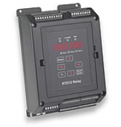
The TE-RTD12 Relay device adds advanced RTD (Resistor Temperature Detector) and differential current monitoring capability to your new or existing motor system. The TE-RTD12 Relay device offers 12 built-in RTD inputs, 3 programmable output relays (5A), 2 isolated analog inputs (4-20mA), 1 isolated analog output (4-20mA), 3 isolated digital inputs, and differential current feedback monitoring.
Additionally, an RS485 (2 wire) communication port is available for use with a master device (PLC / SCADA / Operator Interface) for the purpose of programming and/or monitoring.
Programmable relay outputs are provided that can be configured for a system function or for use as a global Alarm or Trip based on temperature readout, which can be entered in ºC or ºF.
A built-in event recorder stores fault history of past events with data points including Alarm / Trip Code, Current / Temperature value, Analog input value and Date / Time Stamp.
The TE-RTD12 Relay device can be mounted on a back panel using the mounting bracket or DIN-Rail mount.
|
RTD Inputs
Digital Inputs (3 Isolated)
Digital Outputs (3 Relay Form C)
Analog Inputs 4 - 20mA (2 Isolated)
|
Analog Output 4 - 20mA (1 Isolated)
Differentional CT Feedback Monitoring
Fault History / Event Log
|
| Specifications | |
| Control Voltage | 110 - 240 Vac |
| Inputs |
12 RTD inputs (Pt100, Ni100, Ni120, Cu10) |
| Outputs |
3 programmable form C Relays with 5A contact rating pilot duty |
| Keypad |
Two 4-digit displays, one for the RTD name (St1, St2, Fb, rb…) and one for the temperature. |
| Differenctial CT's |
Primary 5 - 2000A |
| Resolution / Accuracy | Analog Inputs better than 1%, Analog Outputs better than 0.5% |
| Communication Port | 2 Wire RS485* |
| Serial Protocol | MODBUS RTU |
| I/O Terminals | Removable terminal blocks |
| Operating Temperature | 32ºF – 122ºF / 0ºC to 50ºC |
| Storage Temperature | -4ºF – 176ºF / -20ºC to 80º |
| Humidity | 10% to 90% (non-condensing) |
| Approvals | UL, CUL |
| * RS485 and Digital Inputs share a common ground point | ð All analog I/O share a common ground point. |